Comparison of Condensers in Chillers: Which Type to Choose and When

Introduction
The condenser is one of the key components of the chiller refrigeration cycle. It is where heat is transferred from the refrigerant to the environment – water or air. The efficiency of this process determines not only the energy efficiency of the plant (EER, COP), but also the overall reliability, compressor stability and operating costs throughout the life cycle of the equipment.
When selecting a chiller, engineers traditionally focus on compressor type, refrigerant, and control system, but condenser type often determines the actual economics of operation. The different designs – shell and tube, plate and air condensers – differ not only in their heat transfer principle, but also in their maintenance requirements, sensitivity to fouling, weight, noise characteristics and operating costs.
Each condenser type has its own design features that determine where it performs best:
- shell and tube – in industrial and process systems with constant loads and stable water supply;
- plate – in compact medium capacity chillers where size and cost are important;
- air – in autonomous systems and facilities without water infrastructure.
Below we will look in detail at each type of condenser, its design, materials, operating features and factors affecting durability and efficiency. At the end there will be a summary comparison on key parameters: energy efficiency, weight, cost of ownership, maintenance, life and aftermarket behaviour.
Shell and tube condenser
Shell and tube condensers are the most common solution in water-cooled chillers. They are used in units from 200 kW to several megawatts and provide the optimum combination of mechanical strength, durability and stable heat transfer under variable conditions.
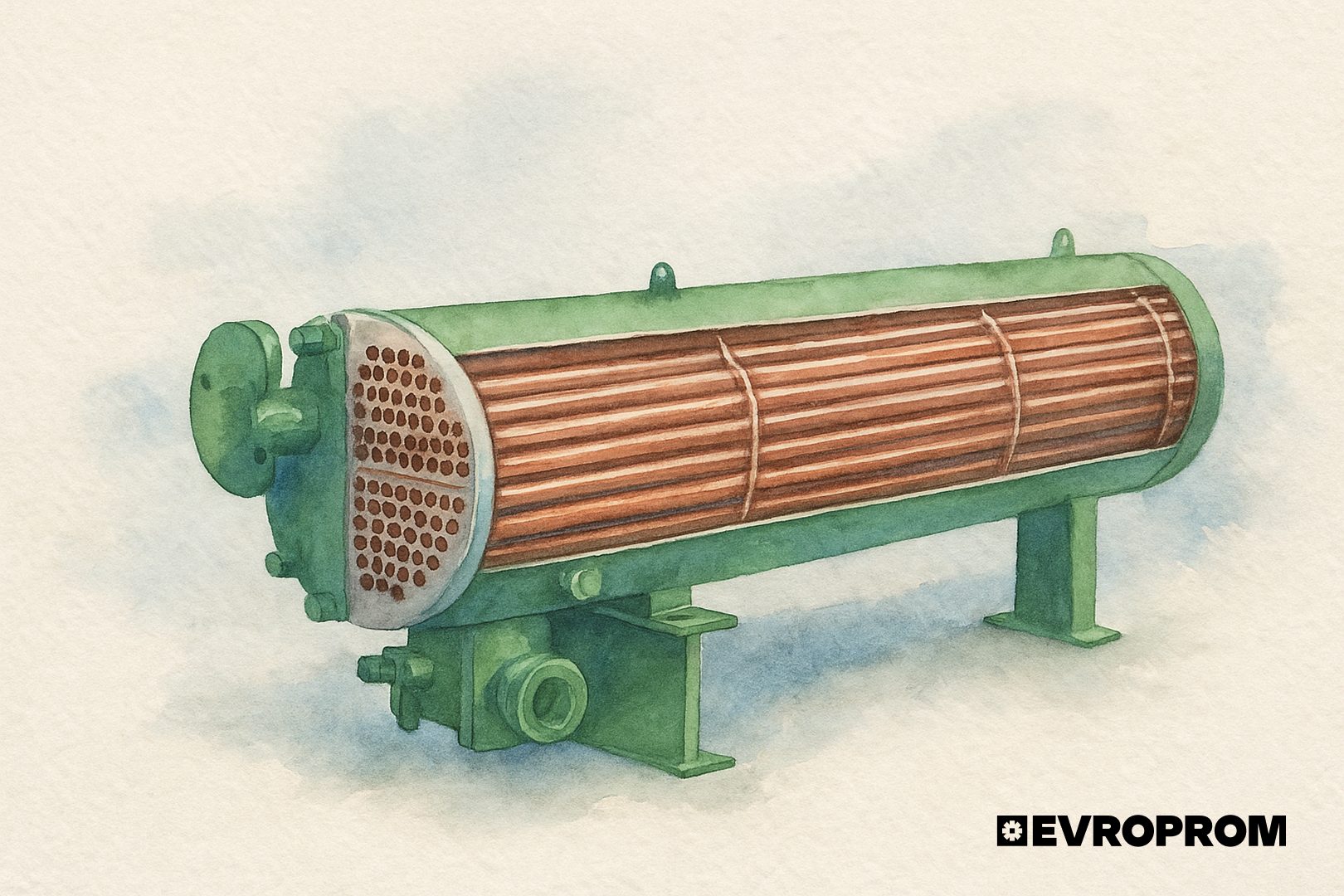
Refrigerant vapour enters the intertube space where it condenses on the outer surface of the tubes, giving up heat to the water flowing inside. The condensate drains to the bottom of the casing, which often acts as a receiver.

Figure 1. Shell and tube condenser in cross-section

Fig 2. Shell and tube condenser – flow diagram
The average heat flux density for shell-and-tube condensers of industrial chillers is 4-8 kW/m², depending on the type of refrigerant and cooling mode. In comparison, plate units develop 10-15 kW/m².
In a clean state, the heat transfer coefficient of a shell-and-tube apparatus for R134a refrigerant is 1,500-2,500 W/(m²-K). However, even with small scale deposits, the thermal resistance increases dramatically.
- At 0,1 mm thickness contamination the thermal power decreases by 5-7 %.
- At 0.3 mm – by 15-20 %.
- At 0.5 mm – up to 30 % drop in performance.
Water with salinity above 300 ppm without softening accelerates the formation of deposits and requires flushing every 6-12 months. The use of glycol solution (30-40 % propylene glycol) reduces the heat transfer coefficient by another 10-12 %, as the viscosity and heat capacity of the mixture is worse than that of water. Therefore, when designing a system with a shell-and-tube condenser in conjunction with dry cooling towers, the increased hydraulic resistance is taken into account and the temperature head calculation is adjusted.
Typical shell and tube condenser failures can be categorised into three groups:
- Mechanical damage
- Tubes rubbing against the baffles in case of weak fixing.
- Vibration cracks in the inlet and outlet areas of the grilles.
- Deformation of tubes after hydrostatic shocks when pumps are stopped.
- Corrosion processes
-
- Localised erosion of copper pipes in the cavitation zone at flow velocities >2 m/s.
- Electrochemical corrosion in the presence of stray currents (especially in contact with brass fittings or dissimilar metals).
- Intergranular corrosion at stainless steel tube welds if passivation is poor.
- Tightness and fatigue defects
-
- Microcracks in tube grids during cyclic heating/cooling.
- Cracking of epoxy coatings inside the casing after 5-7 years of operation.
- Loosening of flange seals after annual service disassembly.
The critical age for shell and tube units is considered to be 10-12 years of active operation without major overhaul. After this age the probability of leaks and localised corrosion increases sharply. During inspection, the wall thickness (minimum 70 % of nominal value), cavitation cavities, tightness of seams are assessed.
With good water treatment and annual chemical flushing, the service life can reach 15-20 years without major overhaul.
Shell and tube condensers are used in various configurations of heat removal circuits:
- Open cooling tower is the most common solution. Requires an intermediate heat exchanger to prevent tube fouling.
- Dry cooling tower – suitable for moderate outdoor temperatures and water limitations, but requires glycol and a higher condensing temperature, which reduces EER.
Global brands rarely manufacture shell and tube units entirely in-house.
- Trane, YORK (Johnson Controls), Carrier – have their own assembly lines but use tube bundles and blanks produced by third party suppliers.
- Daikin and Climaveneta (Mitsubishi Electric Group) use OEM components from Onda, Güntner, SWEP and ThermoKey, adapting the design to a specific capacity range.
- Onda (Italy) and ECO (Spain) are the largest independent manufacturers of the shell and tube condensers used in most European brand chillers.
- Large tonnage installations (>1 MW) often use Bitzer, GEA and AKS HeatExchangers designed for ammonia and refrigerants.
Plate condenser
Plate condensers are widely used in water-cooled condenser chillers where high heat flux density and compactness are required. Compared to shell and tube condensers, they have 3-4 times higher heat transfer coefficient with 10 times smaller dimensions, but are more sensitive to fouling and water quality.
The basis of construction is a pack of thin fluted plates, soldered or welded together to form alternating channels for water and refrigerant. The turbulent flow regime in narrow channels (0.8-2 mm) creates a high local heat transfer coefficient and heat flux density of up to 10-15 kW/m.
In the plate apparatus the refrigerant condenses on one side of the plate, while on the other side water or glycol moves along the contour channels. Due to turbulence, heat exchange is maximally intensive even at low temperature head (2-3 °C). Channel cross-section and corrugation geometry are selected depending on the viscosity and velocity of the flowing medium: for water – corrugation angle 60-65°, for glycol – 40-45°.
The plates are made of stainless steel AISI 316L (thickness 0,4-0,5 mm), for aggressive media – of titanium or nickel alloys. The quality of the gasket or soldering is extremely important, as any micropore between the channels will lead to refrigerant leakage into the water circuit.

Fig 3. Half-welded heat exchanger plate

Fig 4. Copper brazed heat exchanger
Copper brazed plate condenser (BPHE)
The most common type for chillers up to 500 kW. The plate pack is soldered with copper or nickel solder in a vacuum furnace. Copper solder provides good heat transfer, but limits use in environments where copper corrosion is possible (ammonia, chlorides). Nickel variants are used for aggressive liquids or high temperatures up to 200 °C.
Advantages: compactness, low price, high heat flux density (up to 20 kW/m²).
Disadvantages: unrepairable – any defect requires replacement of the unit.
Semi-Welded Plate Condenser (Semi-Welded PHE)
Combines welding and sealing. The plates are argon-arc welded in pairs to form sealed channels for the refrigerant, and gaskets are used on the water side. This makes it possible to service the unit and at the same time exclude freon leakage. Operating pressure up to 30 bar (on the refrigerant side), temperature up to 180 °C.
Gasketed plate heat exchangers (Gasketed PHE)
Not used as condensers due to the risk of seal extrusion at freon pressures, but are used in hydronic modules and recuperators as intermediate heat exchangers.
Average thermal performance
| Indicator | Value |
| Heat transfer coefficient (clean) | 3,000 – 6,000 W/(m²-K) |
| Heat flux density | 10 – 20 kW/m² |
| Working pressure | 25 – 35 bar |
| Refrigerant temperature | up to 150 °C |
| Plate thickness | 0.4 – 0.5 mm |
| Temperature head (∆Tmin) | 1,5 – 2 K |
| Reduction of performance at 0.1 mm contamination | 8 – 10 % |
| At 0.3 mm (moderate fouling) | 20 – 25 % |
| Loss of efficiency at 40 % glycol | 12 – 15 % |
| Design life | 6 – 10 years |
Air condenser
Air-cooled condensers are used in chillers where centralised water cooling is not available or where a stand-alone solution is required (roof-top, modular units, stand-alone industrial facilities). The condenser is a lamella or microchannel type heat exchanger blown by a group of fans. The main design requirements are maximum heat transfer with limited dimensions, controllability of the fan group and durability of the surface under ambient conditions.

The share of fans in the total power consumption of a chiller varies widely: at low and medium outdoor temperatures, fans provide 10-20 % of the total consumption, at extreme warm conditions their share can rise to 30-40 % (especially in units with a large number of axial fans). For a typical mid-range roof-top chiller, 15-20 % of the total installed capacity is a practical value.
EC fans (Electronically Commutated) reduce the consumption of the fan group due to the higher efficiency of the electric motor with frequency control. They precisely control the speed according to the condensing temperature/pressure. The practical effect is a 20-35 % reduction in fan consumption compared to AC motors with frequency converter for the same operating requirements. In addition, EC fans offer better noise control and allow the realisation of “night” and “weather” control schemes.
Fins pitch is a key parameter of an air-cooled condenser. Standard values for selection:
-
- dense range: 1.5-2.0 mm – high heat transfer in clean environments;
- standard: 2.0-2.5 mm – efficiency/dust resistance compromise;
- sparse: 3.0-4.0 mm – for dusty or marine environments, easier to clean;
- very sparse: >4.0 mm – rarely used, reduces compactness.
If the lamellae are clogged, the reduction in air condenser performance is typically 5-15% for light clogging and 20-40% for heavy clogging; the increase in airflow resistance leads to higher fan speeds and higher condensing pressure. Regular flushing of the blades (high water pressure or chemical washing) can restore 80-95 % of the original capacity with timely maintenance.
Microchannel condensers as an alternative to classic fin condensers
Structurally, microchannel capacitors are flat aluminium blocks with integrated microchannels and an aluminium housing. Heat transfer is ensured by thin channel walls and thin lamellae.

Fig. 5.Microchannel capacitor in cross-section
Application of microchannel condensers allows to reduce the heat exchange surface area by 55% on average. Microchannel condensers also allow to reduce the refrigerant capacity of the refrigeration system, because at the same capacity they have 50-70% smaller internal volume

Fig. 6. Comparison of heat exchange surface area of microchannel and standard copper-aluminium air condensers

Fig. 7. Comparison of the internal volume of microchannel and standard air condensers
Among the disadvantages it is worth mentioning that their repairability is very limited: in case of a breakdown it is more common to replace the whole unit. Sensitivity to corrosion and to mechanical damage to the fins/channels; aluminium requires a reliable anti-corrosion coating for aggressive environments (sea air approx.).
Frequent malfunctions and failure points of air-cooled condensers
- Fan and motor failures are the most common cause of unscheduled repairs: bearings, condensation in the motor guard, electro-mechanical defects. Poor blade balance results in vibrations and as a consequence accelerated wear.
- Damage to blades – mechanical impacts, corrosion, deterioration of blowing and localised refrigerant leaks.
- Leaks in the heat exchanger surface – more often in microchannel blocks or in the place of soldering of tubes in lamella heat exchangers.
- Clogging and icing (in humid conditions) – leads to a drop in air flow capacity and an increase in condensing pressure.
- Corrosion of drain pans and frame – localised leaks in the electrical compartments of the fans.
Planned service life (under normal conditions) for a properly made and properly coated lamella section – 10-15 years; for microchannels with quality coating and absence of mechanical damage – 8-12 years.
During selection it is important to check: type of coating, availability of service documentation for fan replacement, modular replacement of sections and ease of dismantling/re-installation.
Comparison of condenser types
The choice of condenser type is a key engineering step that determines not only the energy performance of the chiller, but also its operating strategy. Below is a systematised comparison of the three main types – shell and tube, plate and air – based on a combination of thermal, design and operating parameters.
Summary comparison table
| Parameter | Shell and tube | Plate | Air |
| Cooling type | Water | Water | Air |
| ∆Tmin (temperature difference) | 4-6 K | 2-3 K | 6-10 K |
| Wall thickness of the heat exchange surface | 0.8-1.2 mm (tube) | 0,4-0,5 mm (plate) | 0,2-0,3 mm (lamella/channel) |
| Weight (for 500 kW) | 400-600 kg | 40-60 kg | 500-800 kg (with fans) |
| Dimensions | large | minimum | large |
| Service life | 12-20 years | 6-10 years | 8-15 years |
| Performance drop with contamination | 10-20 % (0.3 mm deposits) | 20-25 % (0.3 mm) | 10-40 % (lamella clogging) |
| Sensitivity to water quality | moderate | high | absent |
| Maintenance requirements | mechanical and chemical cleaning | CIP-washing, leak test | lamella washing, fan replacement |
| Noise characteristics | low | low | medium/high (70-85 dB(A)) |
| EER reduction at glycol (40 %) | -10 % | -12-15 % | not applicable |
| Manufacturing cost (CAPEX) | high | low/medium | high |
| Cost of maintenance (OPEX) | medium | low | high |
| Application | industrial and large facilities | medium and compact chillers | stand-alone units, rooftops |
| Used market, residual life | high demand, up to 10 years after revision | low, rarely repaired | medium, corrosion dependent |
| Compatibility with cooling towers | direct/through heat exchanger | via hydronic module | not required |
| Installation requirements | solid base, vibration compensation | minimum | protection against wind, vibration, noise |
Going further, from a direct comparison of technical values, and based on them, to application scenarios, we propose to consider examples of conditions and constraints that will guide us in favour of one or another type of condenser:
| Constraint | → | Solution |
| Technical floor with load limitation in the floor slabs, building structures are not designed for heavy equipment. | → | Plate condenser – minimum weight, compact size, no vibration. |
| Production plant with existing cooling tower, requires integration into a water system already running on recycled water. | → | Shell and tube condenser – resistant to fouling, repairable, works well with non-ideal water. |
| Object without access to water (shopping mall roof, logistics centre, data centre), high viscosity of the heat transfer medium reduces heat transfer. | → | Shell and tube condenser – larger hydraulic pipe diameter, less pressure drop and risk of freezing. |
| Compact installation in machine room or basement, limited space and low room height. | → | Plate condenser – high heat transfer density, easy to fit into small layout. |
| Roof installation in hot climates, high temperature head, risk of overheating. | → | Air condenser with EC fans and microchannel sections – increased thermal efficiency and speed control. |
| Marine or coastal area, corrosive atmosphere, salt spray. | → | Shell and tube condenser in titanium or stainless steel or air condenser with Blygold/E-coat coating. |
| Temporary or mobile chiller (rental, seasonal installation), mobility and ease of maintenance required. | → | Air condenser – independent of external systems, does not require hydronic pipework. |
| Data centre with 24/7 load and high reliability requirements, critical load 24/7, no downtime. | → | Shell-and-tube or semi-welded plate condenser in closed circuit with dry cooling tower – high stability, can be connected in parallel to a redundant cooling tower |
Conclusion
The condenser determines not only the energy efficiency but also the operating strategy of the chiller. Shell and tube units offer maximum reliability and maintainability, plate units offer compactness and high heat transfer coefficient, air units offer autonomy and easy installation.
The optimal choice depends on the operating conditions: water availability, weight, noise and service requirements. A properly selected condenser type ensures stable operation and economic efficiency of the system throughout the entire life cycle of the chiller.
Ultimately, the right choice of condenser is a balance between energy efficiency, maintainability and environmental sustainability, which the engineer should consider at the design stage. Understanding the physical processes, degradation rates and diagnostic techniques not only allows you to select a unit, but also to ensure that it operates at its designed efficiency for its entire service life.
If you still have questions on equipment selection, please contact Europrom specialists. We will help you to choose a suitable solution and offer reliable chillers presented in our catalogue.
![]()
What you get with EVROPROM
Professional technical selection: we take into account the operating parameters, environment, operating conditions and system configuration – we offer the optimal solution for the specific task.
Engineering expertise and advice: we explain the pros andcons of each option in terms of reliability, maintenance, energy efficiency and service life.
A catalogue of proven equipment: a wide range of shell-and-tube and plate heat exchanger chillers from reliable manufacturers, adapted to industrial and commercial applications.
Reduced operational risks: with the right heat exchanger design, you minimise the chance of leaks, overheating, freezing or loss of efficiency.
Economies of ownership under control: optimise installation, maintenance and energy costs over the life of the equipment.

Author of the article:
Andrey Kohan, refrigeration equipment engineer
22.10.2025